- Mark as New
- Bookmark
- Subscribe
- Mute
- Subscribe to RSS Feed
- Permalink
- Report Inappropriate Content
Hi,
I was constraining an interface between a stratix II device and a digital to analog converter. Trying to close timing gave me quite a few problems. I now have a timing report free of warnings and I wanted to give a brief outline of what I have done and perhaps someone can comment and tell me if I am on the right track (as I have done one or 2 things which I hadn´t tried before). Basically a clock from the DAC of 150MHz enters the FPGA, this clock is used to clock the rdclk pin of a DCFIFO, so the idea is that on every rising edge a new word will be clocked out to the parallel data bus of the DAC from the FIFO. The DAC can be configured to latch the data on either the rising or falling edge of this same clock, I have elected to use the falling edge in order to give me some extra time. To constrain the interface, I defined a virtual clock of the same frequency as the main clock coming from the DAC but inverted due to the fact that the DAC will latch the data on the bus on the falling edge. create_clock -name {DAC_PLLLOCK} -period 6.666 -waveform { 0.000 3.333 } [get_ports {DAC_PLLLOCK}] create_clock -name {PLLLOCK_Virtual} -period 6.666 -waveform { 3.333 6.666 } The DAC data bus requires a setup time of 0.5ns and a hold time of 1.5ns, therefore I put in place the following set_output_delay constraints: set_output_delay -clock { PLLLOCK_Virtual } -max 0.5 [get_ports {DAC_D*}] set_output_delay -clock { PLLLOCK_Virtual } -min 1.5 [get_ports {DAC_D*}] After running a timing report, on the slow model setup failed by around 6ns so I figured this was due to the fact that I was reading the data from the FIFO and placing it on the databus on the rising edge while timequest assumed that the DAC would latch it on the falling edge 3.3ns later. To overcome this I set a multicycle path between the 2 clocks as follows: set_multicycle_path -from [get_clocks {DAC_PLLLOCK}] -to [get_clocks {PLLLOCK_Virtual}] -setup -start 2 Now after running the timing anaylsis I meet timing just about. I would be very grateful if someone could let me know if I am on the right track with how I have constrained this interface? Is the placing of the multicycle the correct thing to do? or does it have an adverse affect that I have failed to see? Is it ok to do it with a virtual clock? Please let me know of any other oversights on my part in constraining this interface that you may think of. Many thanks once again for any suggestionsLink Copied
- Mark as New
- Bookmark
- Subscribe
- Mute
- Subscribe to RSS Feed
- Permalink
- Report Inappropriate Content
Sorry, Ardni, but I have some doubts. If you specify multicycle=2 you tell TimeQuest that from the time the source register is clocked anything is allowed to happen (i.e. data invalid) on the input of the destination register until Tsu before the second clock edge of the destination clock. This only works if you have an enable on the destination register which you know (from the logic of your design - perhaps a state machine) will not be enabled during the first clock edge of the destination register.
In your case the destination register is external (in the DAC) with no enable. You care about what data is on the register input at every clock cycle, therefore multicycle is not appropriate. Coincidentally I am currently wrestling with a project I inherited where the designer misused multicycles in the same way. It is great for making the timing violation seem to go away - for a while :-). What to do? I recommend you clock the DAC on the same edge as the source register. By using the opposite edge you perhaps gave yourself less time. You may also want to add extra delay in your set_output_delay statements reflecting the trace delay on your board, i.e. the tracks between the two chips. I am hoping someone cleverer will check what I have just written, and comment.- Mark as New
- Bookmark
- Subscribe
- Mute
- Subscribe to RSS Feed
- Permalink
- Report Inappropriate Content
On SlowClock's comment, a multicycle of 2 in TimeQuest does not double the window in which you can pass data(i.e. a clock enabled transfer). A setup multicycle of 2 shifts the window you're targeting. For example, if you have a 10ns clock feeding the source and destination registers, the default setup requirement is 10ns and the hold requirement is 0ns. A multicycle -setup 2 will make the setup requirement 20ns, but will also shift the default hold requirement to be a positive 10ns. So it's still a 10ns window you're transfering data through, just on the next edge. If you want to make the window grow, you would have to add a multicycle -hold 1 to the same path, and thereby the hold requirement would stay at 0ns.
In the Classic Timing Analyzer, this was not the case, where a setup multicycle of 2 would make the setup requirement 20ns but the hold requirement would stay at 0ns. The reason for this is a global setting under Timing Analysis -> More Settings that tells the Classic Timing Analyzer to secretly add a hold multicycle whenever a setup multicycle is added. So the coment is true for Classic, but not TimeQuest. (I've posted a presentation on TimeQuest multicycles to this forum, that might help clear up what's going on...). As for advice, first thing is that clocking on the falling edge(before the multicycle) hurts your setup requirement, but helps your hold. But your data will be coming from a memory block to the output register, which means you'll have a long setup time. If at all possible, I recommend registering your data on the way out. That alone should get it to meet timing. I would also change the behavior of the DAC to latch on the rising edge. You're going to easily meet the hold requirement just because you have positive delays to get the data out of the FPGA, and it's the setup requirement that could be difficult.- Mark as New
- Bookmark
- Subscribe
- Mute
- Subscribe to RSS Feed
- Permalink
- Report Inappropriate Content
Thank you SlowClock and Rysc for the replies.
Initially I was unsure about the legality of implementing the multicycle as I did and still I do not have it clear in my own head. Here is what is confusing me: Rysc you said that "clocking on the falling edge(before the multicycle) hurts your setup requirement, but helps your hold". I am clocking the data from the FIFO to the DAC data bus on the rising edge, so would this multicycle not help my setup time (if the DAC registers on the falling edge) ? i.e. it gives me an extra half cycle and with a 150MHz clock give me a default setup time of 9.99ns up from 6.66ns? I didn´t really understand what you meant by "I recommend registering your data on the way out"? Do you mean removing the multicycle and clocking on the following rising edge. Without the multicycle it seems to be very difficult to meet setup time. I am still not 100% clear if using the multicycle as I have is illegal, if it is merely shifting the same size window by one cycle, then it should be ok? I´m probably wrong but I´d be grateful if someone could clarify these points. Many thanks for the help so far.- Mark as New
- Bookmark
- Subscribe
- Mute
- Subscribe to RSS Feed
- Permalink
- Report Inappropriate Content
I have these background info that may help.
1) First check your DAC datasheet. if you are lucky your dac (if advanced type)may have auto timing adjustment. In that case, you can keep TimeQuest relaxed. 2) Your interface is not the classic source synchronous. Your Dac clk is opposite that of its data. For TimeQuest source synchronous modelling, You might consider your virtual clk to represent a non-existing clk that goes to DAC with data. This clk will should cancel the board delay with respect to actual DAC clk(inside DAC). The physical DAC clk travels first to FPGA then data goes back to same clk inside DAC. So adjust phase of this virtual clk accordingly. 3) The important issue to you should be optimisation rather than getting Tsu/Th as requested. Even if Quartus gets your Tsu/Th it must optimise it in the middle of valid timing window!! otherwise there is no point in the whole technology. The optimum point is here: DAC Tsu is .5 and Th is 1.5 (incidentally you might be wrong here, Th is usually very small) then your valid window is 6.7 -(.5 + 1.5) = 4.7. FPGA must output data at the mid point of this valid window i.e. at 1.5 + 4.7/2 = 3.35 with respect to virtual clk edge Th*** valid window***Tsu ------ --------------- ---- ...................|................. I am not used to TimeQuest yet but with classic timing I will set the Tco directly on data and must achieve it. If not I use a PLL until achieved. I agree with the issue of falling/riding edge being not necessry and complicating. Multicycle has no place here.- Mark as New
- Bookmark
- Subscribe
- Mute
- Subscribe to RSS Feed
- Permalink
- Report Inappropriate Content
Alternative to virtual clk is adjust Tsu/Th of DAC as seen at FPGA and enter new values in timequest
- Mark as New
- Bookmark
- Subscribe
- Mute
- Subscribe to RSS Feed
- Permalink
- Report Inappropriate Content
kaz is right in that you're not doing source-synchronous, i.e. you're not sending the clock off chip, but using an external clock to drive the FPGA and DAC. (And right now I'm assuming they're matched delays to each device, as that's the way it's modeled). If you're sending a clock off-chip, then we need to start over...
As for clocking on the falling edge, let's go back to my example. When both the source and destination registers are rising edge-triggered, then the setup requirement is a full clock period, 10ns, and the hold requirement is 0ns. If the external device clocks on the falling edge(which you've modeled by saying the external clock's -waveform has a 180 degree shift), then the default setup requirement is 5ns and hold requirement is -5ns. So you've made the setup requirement tighter and the hold requirement looser. If you're intention was to go to the next window, then add: set_multicycle_path -setup -to [get_clocks PLLOCK_VIRTUAL] 2 This would make the setup requirement 15ns and the hold requirement 5ns. Make sure you go to assignments -> settings -> Fitter and have Optimize Hold Timing checked and Multi-Corner Analysis checked, as you have a positive hold requirement. My comment about registering on the way out is that pretty much all fast I/O interfaces use the dedicated I/O registers. These give the best performance, and they all match nicely across the bus. You're using a memory as your output register, which will have a long delay to each I/O, it won't match nicely, etc. It might work with this setup, I'm just stating the general practice is to register the I/O. Most importanly, you need to be able to do: report_timing -setup -npaths 50 -detail full_path -to_clock PLLLOCK_VIRTUAL -panel_name "s: -> PLLLOCK_VIRTUAL" report_timing -hold -npaths 50 -detail full_path -to_clock PLLLOCK_VIRTUAL -panel_name "h: -> PLLLOCK_VIRTUAL" This analyzes all of these outputs and reports the whole analysis. It takes a bit to understand, but once you get what everything means, you can deconstruct what you want and make sure it matches how your interface works. In my opinion, this is probably the most important skill that just isn't documented well enough.- Mark as New
- Bookmark
- Subscribe
- Mute
- Subscribe to RSS Feed
- Permalink
- Report Inappropriate Content
Thank you again for the replies.
After reading the post by Kaz I tried to meet timing without using the multicycle. I was unable to meet timing by about 1.5ns. I wanted to use a PLL to put a couple of ns negaitve shift on the clock coming in, but unfortunately due to an oversight, this clock is not on a dedicated clock line. I resorted to the multicycle approach as before and am now registering the data beforehand as recomended by Rysc. I am happy enough with the results except one thing is still confusing me. I don´t have any problems meeting the setup time comfortably, but when it comes to the hold time I am having a little trouble understanding how timequest is doing its calculations. In my sdc file I have the following constraints in place: create_clock -name {DAC_PLLLOCK} -period 6.666 -waveform { 0.000 3.333 } [get_ports {DAC_PLLLOCK}] create_clock -name {PLLLOCK_Virtual} -period 6.666 -waveform { 3.333 6.666 } set_output_delay -clock { PLLLOCK_Virtual } -max 0.5 [get_ports {DAC_D*}] set_output_delay -clock { PLLLOCK_Virtual } -min 1.5 [get_ports {DAC_D*}] set_multicycle_path -to [get_clocks {PLLLOCK_Virtual}] -setup -end 2 So my default hold time should be 3.33ns but taking into account the 1.5ns th requierment in the datasheet, it will be 4.83ns by my understanding. (Writing data out on rising adge and sampling on the falling + th) Timequest however, when I analyze the data required path, subtracts the 1.5ns from the 3.3ns thus giving a requirment of 1.833ns. I am sure timequest is correct but I cannot understand why it subtracts the hold time rather than add it. I meet the hold requirment comfortably on the slow model, but on the fast model, even though timequest tells me I meet it, I don´t think I do. I have attached a snapshot of the worst case hold slack for the fast model. Timequest tells me that it meets timing but I don´t think it should. Notice how on the required path calculation it subtracts the 1.5ns. I would be grateful if someone could explain this to me. Thanks again for the help.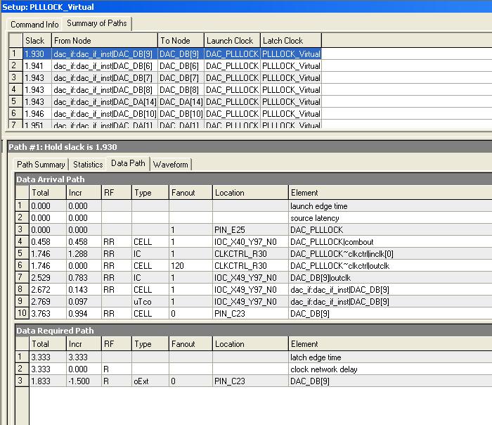
- Mark as New
- Bookmark
- Subscribe
- Mute
- Subscribe to RSS Feed
- Permalink
- Report Inappropriate Content
Ok Rysc, I learnt something basic here. My multicycle understanding was built on the Classic timing analyzer as you guessed. I have manged to avoid them ever since, so the difference escaped me. Thanks.
- Mark as New
- Bookmark
- Subscribe
- Mute
- Subscribe to RSS Feed
- Permalink
- Report Inappropriate Content
My summary for TQ:
1) If you're "expanding the window", i.e. allowing multiple clock cycles for data to go through, you'll have paird multicycles with a setup of N and hold of N-1. For example, if it's a 10ns clock and you want to give 40ns for the data to go through: set_multicycle_path -setup 4 set_multicycle_path -hold 3 2) If you're shifting the window, add a multicycle setup. 99.9% your shifting one cycle, so it's: set_multicycle -setup 2 (Implied is that the hold multicycle is 0, but you could add it if you wanted to be explicit). The common case for this is when phase-shifting a clock a little. For example, if you phase-shift your destination clock forward 500ps, or you phase-shift your source clock back 500ps, the setup requirement between those clocks will be 500ps. Most likely you want your setup requirement to be the next clock cycle. Adding the following will do that: set_multicycle_path -from [get_clocks src_clk] -to [get_clocks dst_clk] -setup 2 Your setup requirement will be one clock period + 500ps, and your hold requirement will be 500ps. (Draw out the waveforms and it makes sense.) 3) You don't have to be an expert. It's really easy to add a multicycle, then immediately run TimeQuest and do a report_timing -setup and report_timing -hold between the two points. Look at the difference between the launch and latch clocks. That's all your affecting. Look at them in the waveform viewer too. If it looks like how your design behaves, great. If it doesn't, change the multicycle values you entered and run again. The process might take a few minutes, but it's pretty easy. Ryan- Mark as New
- Bookmark
- Subscribe
- Mute
- Subscribe to RSS Feed
- Permalink
- Report Inappropriate Content
Very clear now, thanks Rysc. Much obliged.
Any thoughts on the value of using multicycle (= 2) to transition between domains of related clocks of different frequencies? Example: signals passing between domains of Clk_75 and Clk_100 which are both derived from the same 150 MHz clock. I have seen this done but have some doubt about "best practise". My concern is particularly when vectors are passed without any handshaking. One needs to be sure that all bits of the vector arrive on the same clock edge. Is adding handshaking and treating them asynchronously (as unrelated clocks with double registers on the handshake lines) a better option? Perhaps this should have been a different thread - sorry Ardni, if I am highjacking your topic, but one thing leads to another...- Mark as New
- Bookmark
- Subscribe
- Mute
- Subscribe to RSS Feed
- Permalink
- Report Inappropriate Content
You've got a 10ns and 13.333ns period clock. TimeQuest will try to go with the tightest constraint of 3.333ns. Personally I think that is good, and would limit all transfers to be register to register, so that it can easily meet timing. This nicely transfers the whole bus with everything arriving on the same edge. The problem, and this occurs with any solution, is you can't transfer data at the full clock rate, since it's either too fast or too slow than the other clock rate.
If you add a multicycle, you're now potentially passing through multiple edges. You need to know if/when this occurs, and handle it properly. It can get complex quickly. It's definitely do-able, but you need to really plan it out correctly and account for all possible transfers. (And it's hard to say how it will work up front without knowing the data rates, which way you're talking, etc.) But the fact that the clocks are "semi-synchronous" can defeinitely be used to your advantage.- Mark as New
- Bookmark
- Subscribe
- Mute
- Subscribe to RSS Feed
- Permalink
- Report Inappropriate Content
Thanks again, Rysc, for your clear explanation. I looked again at the example I mentioned - a project I inherited. The designer used
set_multicycle_path -setup -start -from [get_clocks clk_a] -to [get_clocks get_clocks clk_b] 2 set_multicycle_path -hold -start -from [get_clocks clk_a] -to [get_clocks get_clocks clk_b] 2 I did could not figure it out at the time, and worked around it with handshaking instead. Perhaps you see some sense it which I could not.- Mark as New
- Bookmark
- Subscribe
- Mute
- Subscribe to RSS Feed
- Permalink
- Report Inappropriate Content
Run report_timing with -setup and -hold between the two clocks to see what the setup and hold requirements are with these multicycles. Naturally, this is what the original designer wanted the paths to be analyzed at. The difficult question is if the design actually behaves this way.
- Mark as New
- Bookmark
- Subscribe
- Mute
- Subscribe to RSS Feed
- Permalink
- Report Inappropriate Content
I will explore that again for the sake of the learning curve. In the mean time the handshaking scheme is working fine, though. You've been very helpful, thanks.
- Subscribe to RSS Feed
- Mark Topic as New
- Mark Topic as Read
- Float this Topic for Current User
- Bookmark
- Subscribe
- Printer Friendly Page